Coorindate Systems in HoloLensARToolKit v0.2
15 May 2017This post is part of documentation of HoloLensARToolKit, version v0.2. The documentation for the coordinate system in HoloLensARToolKit v0.1 is here.
Coordinate System of Unity3D
Unity3D uses left-hand coordinate systems to define transformations.
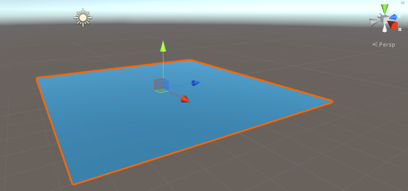
The above is a screenshot of a Unity transformation. The x, y, z axis directions are visualized with different colors, and are following left-land rules. In addition, rotation along axis is applied clockwise, unlike counter-clockwise in right-hand coordinate systems. If you are accustomed to right-hand coordinate systems as I do, please pay more attention when working with raw 4x4 matrices.
Coordinate System of ARToolKit
ARToolKit uses right-hand coordinate systems. Since OpenGL is right-handed as well, it is very comfortable to visualize the tracking result of ARToolKit by OpenGL.
In the official Unity package of ARToolKit, arunity, there exists a utility function
public static Matrix4x4 LHMatrixFromRHMatrix(Matrix4x4 rhm)
that converts the tracking result of ARToolKit to Unity environment.
Coordinate System of HoloLensARToolKit
It took me a while to figure out the complicated conversions happened inside ARToolKit, inside Unity, and in-between. Actually in HoloLensARToolKit v0.1, the coordinate system is not very clear nor consistent between different kinds of markers. In the current version v0.2, the design of coordinate system is improved, and a special Unity scene is designed to help visualize the coordinate system associated with the marker.
In this project, the tracking result is converted into left-handed coordinate system, with y-axis flipped. This is performed in the function ARUWPUtils.ConvertARUWPFloatArrayToMatrix4x4(). When the tracking result is applied to a Visualization Target of the current marker, there is no need to worry about any conversion.
The following examples show the coordinate system associated with each kind of marker.
Single Pattern Marker
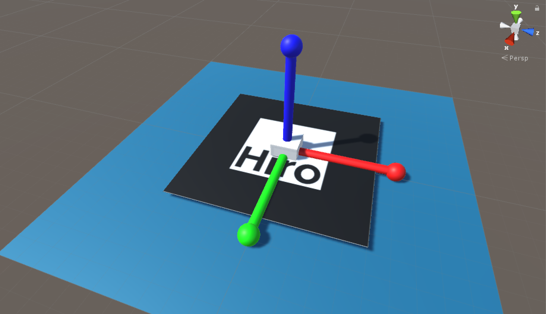
Hiro marker and Kanji marker are examples of single pattern marker. They are defined using binary files.
The coordinate system associated with a single pattern marker looks like this:
Single Matrix Marker
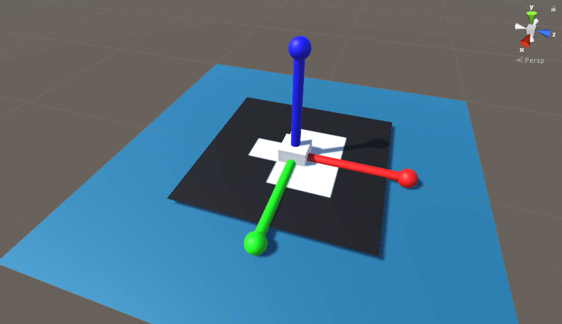
Single matrix marker is pre-defined in ARToolKit. User is only required to provide the ID and type of matrix code associated when using them in applications. A full list of matrix markers are available in ARToolKit repository. The coordinate system associated with a matrix marker looks like this:
Multi Matrix Marker
Multi matrix marker is defined by a configuration file, that contains
- total number of matrix markers
- the ID of each matrix marker
- the transformation from the multi-matrix marker to individual matrix marker.
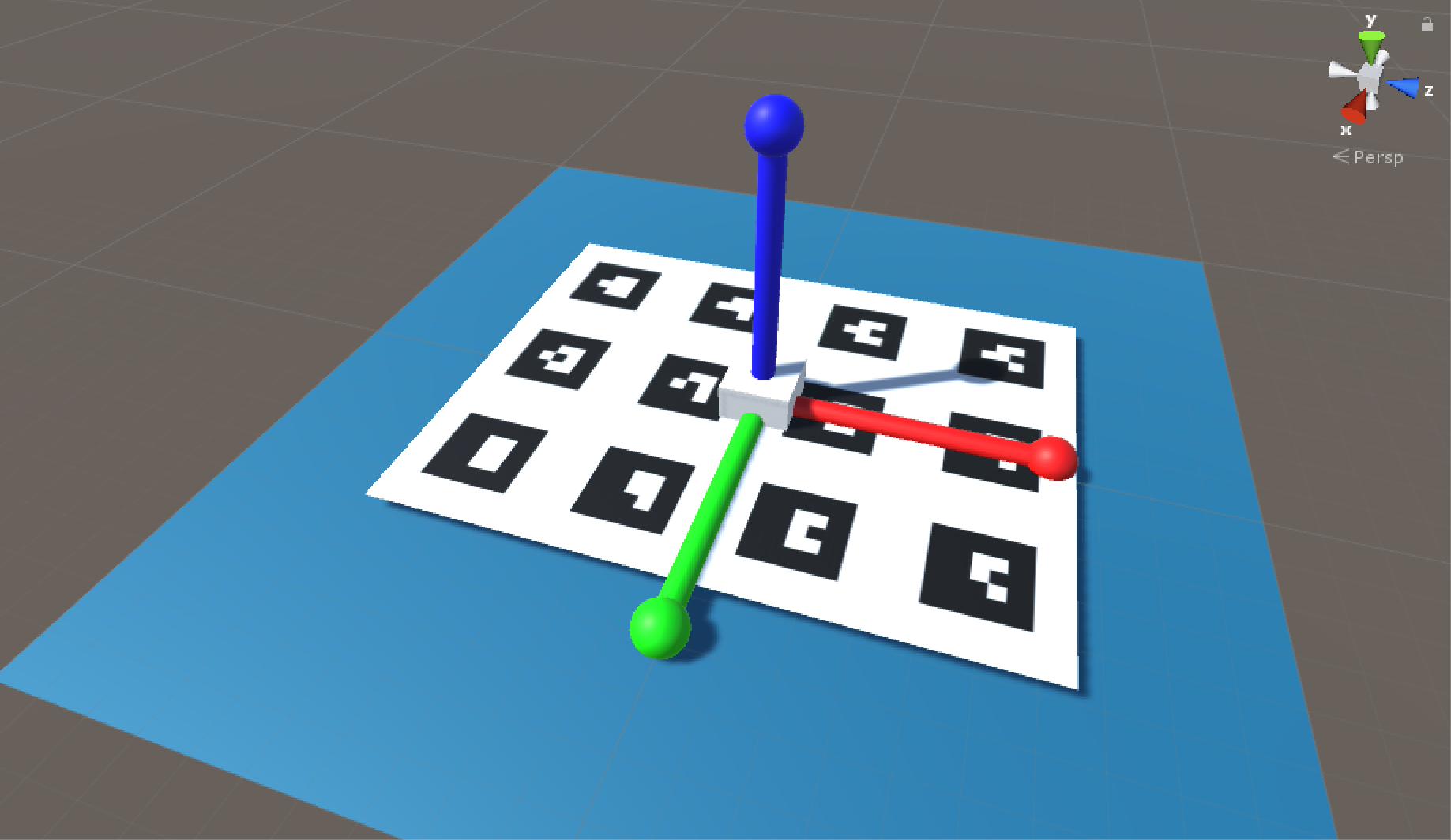
Multi-matrix marker is useful for robust tracking, thus is much more useful for accuracy-critical augmented reality applications. Iterative Closest Point (ICP) algorithm is the underlying method for the fusion of tracking information.
For example, for a multi-barcode-4x3 configuration, the coordinate system of the multi-marker looks like this:
Marker Configuration File
In HoloLensARToolKit v0.1, users need to adjust the multi-marker configuration file provided by ARToolKit, like this, to make it work with HoloLensARToolKit. Starting from v0.2, this step is not needed. The multi marker configuration file of ARToolKit and HoloLensARToolKit is EXACTLY SAME, which means, the description of multi marker is actually using right-hand coordinate system.
Finally
You can access more articles describing the implementation details of HoloLensARToolKit in my blog, simply clicking on the tag:
Thanks for reading!