ARUWPMarker Options in HoloLensARToolKit v0.2
15 May 2017This post is part of documentation of HoloLensARToolKit, version v0.2. The ARUWPMarker options documentation for v0.1 is here.
ARUWPMarker
ARUWPMarker.cs is one of the main scripts used in HoloLensARToolKit. In this post, the options of this script are listed and discussed, along with common usecases.
In Unity project using HoloLensARToolKit package, each actual marker must have one corresponding ARUWPMarker script.
ARUWPMarker is very similar to ARMarker in ARToolKit. However, because currently HoloLensARToolKit does not support NFT (Natural Feature Marker) of ARToolKit, that part of attributes are not included in ARUWPMarker.
When ARUWPMarker script is attached to some Unity GameObject, its inspector window looks like this:

Type
This field configures the type of the current marker. Available options are: single, single_barcode, single_buffer, and multi.
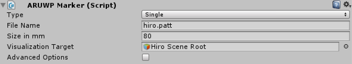
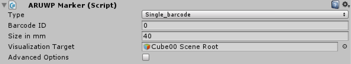
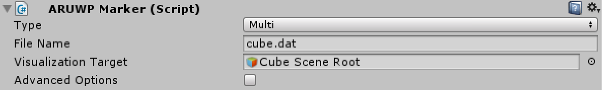
single: single pattern marker, e.g. Hiro marker and Kanji marker. Ifsingleis selected, then the field File Name will appear. Root path of file name isAssets/StreamingAssets/.single_barcode: single barcode marker (as known as single matrix marker). If it is selected, then the field Barcode ID will appear.single_buffer: single pattern marker, but directly specified by a byte buffer. It should be set at runtime using functionARUWPMarker.SetSingleBufferBuffer().multi: multi marker consists of multiple barcode marker. If it is selected, then the field File Name will appear to ask for the configuration file. Root path of the configuration file isAssets/StreamingAssets/as well.
Size in mm
You need to specify the size of the marker (outer border), when single or single_barcode marker is used.
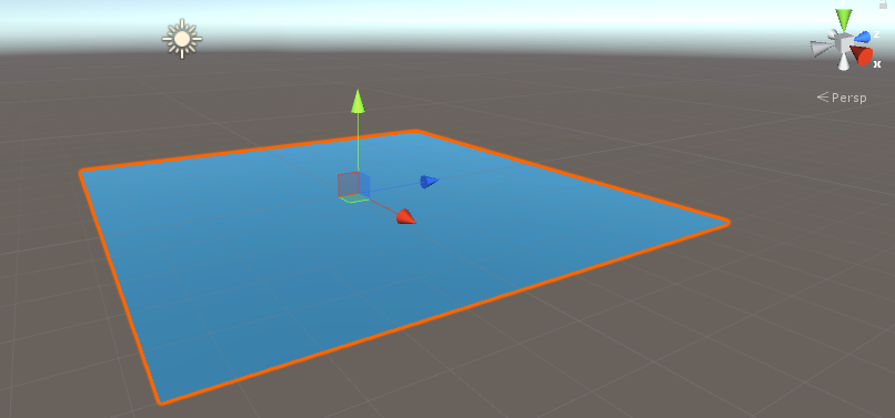
Visualization Target
Marker pose provided by the algorithm contains position and orientation. This information should be applied to some object in the scene so that augmented reality experience is created. This field controls the target GameObject that receives the pose of marker. The common practice is to create an GameObject acting like a sub-scene, and actual 3D model to be overlaid can be attached to this sub-scene. In this case, the root of the sub-scene should be the Visualization Target.
Advanced Options
When this checkbox is checked, more options will appear in the inspector that enables you to configure the behavior of the marker with more freedom. The full list of options are shown below:
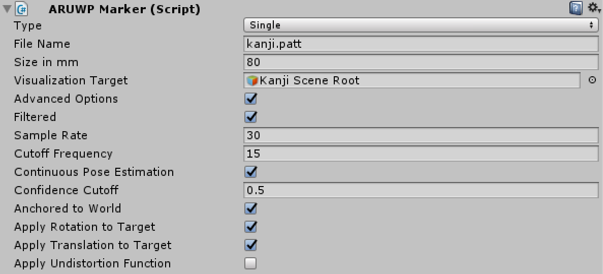
Filtered
If Filtered is checked, filtering options of marker tracking can be configured, including: Sample Rate and Cutoff Frequency. Please refer to ARToolKit documentation for details about filtering.
Continuous Pose Estimation
Please refer to ARToolKit documentation for details about Continuous Pose Estimation.
Confidence Cutoff
Please refer to ARToolKit documentation for details about Confidence Cutoff.
Anchored to World
HoloLens is constantly localizing itself in the room.
The default augmented reality experience of HoloLens is creating an AR scenario within the room, and let the user explore it. Therefore, HoloLensARToolKit package takes advantage of its localization algorithm, to make the virtual object appear in the world coordinate system. The benefit of doing it is that, when the marker is occluded, it stays at the same position in the room. It is desired when the line-of-sight of the HoloLens camera is blocked, but the tracked object is not moving in the environment.
If this field is not checked, then all the pose update is achieved in the camera coordinate system. The virtual object stays at the same pose with respect to the camera, when the tracking is lost.
Apply Rotation
Whether rotation of tracked marker should be applied to the Visualization Target.
Apply Translation
Whether translation (position) of tracked marker should be applied to the Visualization Target.
Apply Undistortion Function
The object to overlay and the marker seens by humans eye sometimes misalign, because the tracking system and the display system are never calibrated with respect to each other. However, if you are able to calculate the misalignment between them, it is possible to manually cancel that misalignment by putting an additional transformation on top of the tracking result. This field is the switch to enable or disable such undistortion. In addition to that, please use ARUWPMarker.magicMatrix1 to set the undistortion matrix of translation, and use ARUWPMarker.magicMatrix2 to optimize the rotation.
For more details about this technique, please refer to our arxiv paper.
Examples
Below are basic usage of three typical markers used in HoloLensARToolKit:
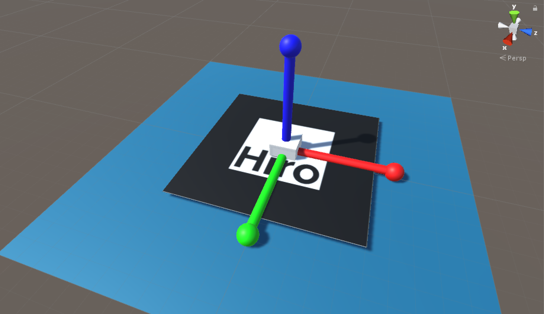
Hiro Marker
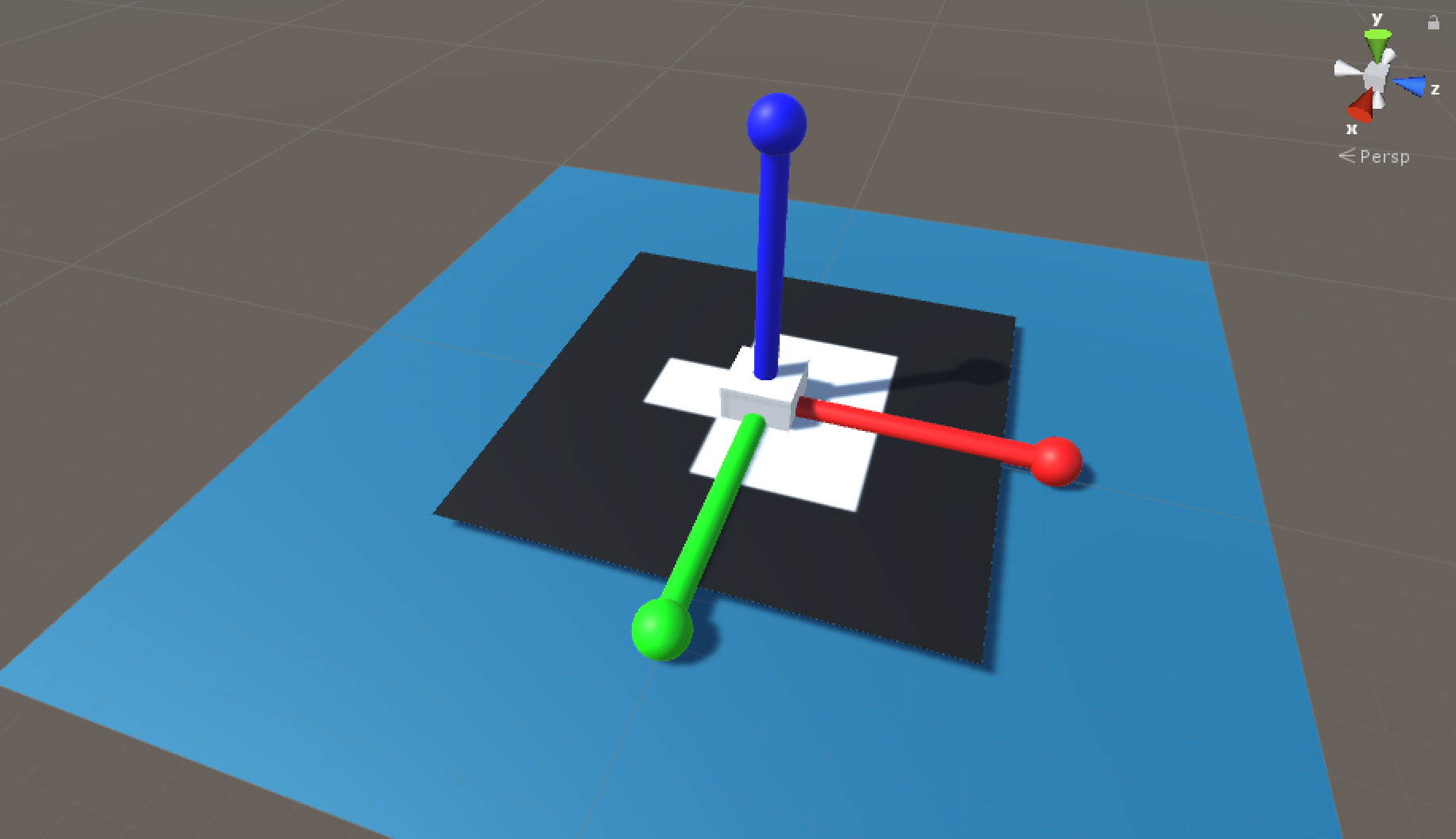
Matrix Marker (Number 0)
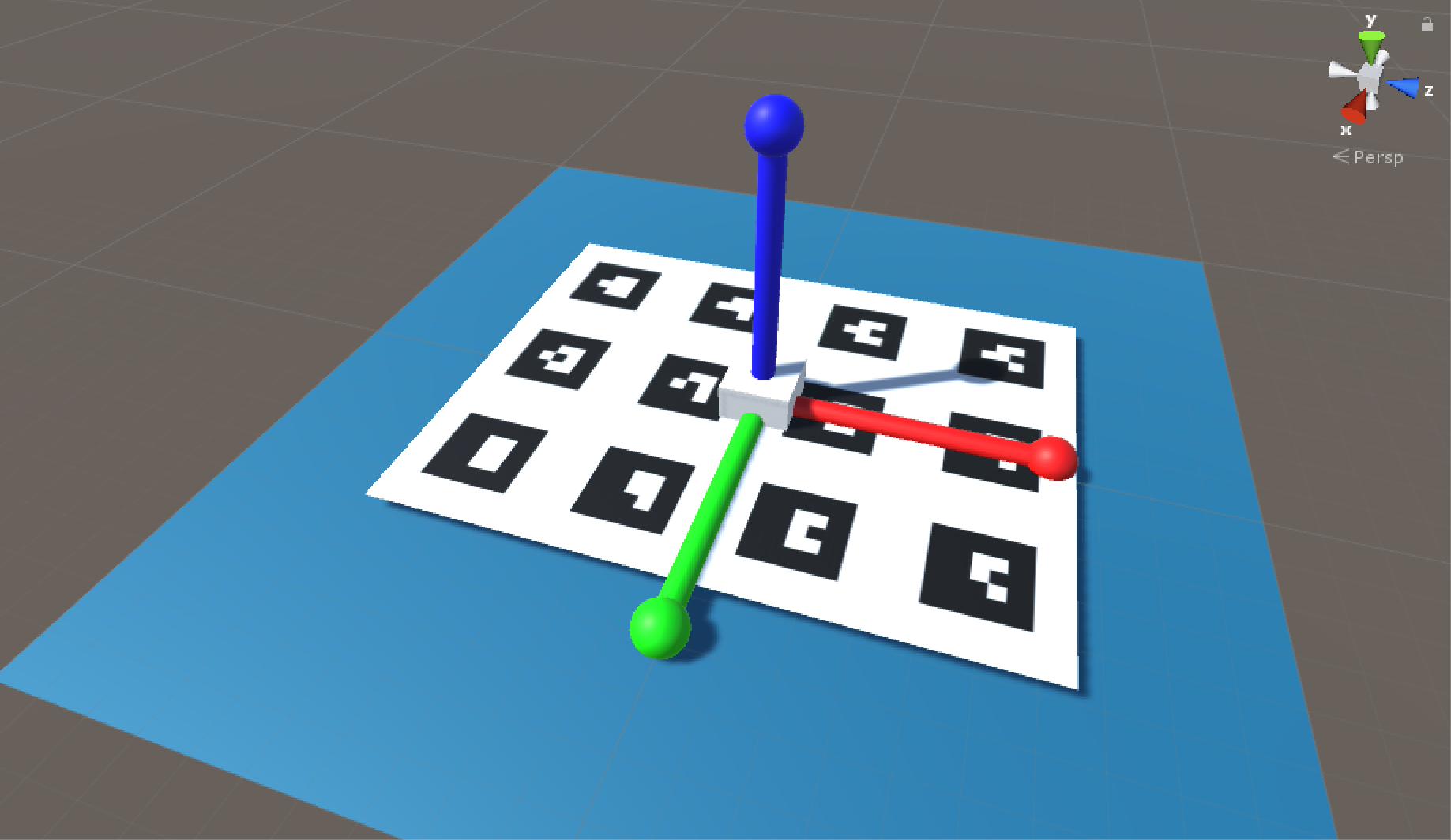
Cube Marker
Finally
You can access more articles describing the implementation details of HoloLensARToolKit in my blog, simply clicking on the tag:
Thanks for reading!